| Author |
 Topic Topic  |
|
|
tomed
France
28 Posts |
 Posted - Apr 07 2015 : 17:36:00 Posted - Apr 07 2015 : 17:36:00


|
Dear Enrico,
Is Fast Henry dealing only with infinite ground plan?
Is there any issues to simulate some track above finite ground plan?
Thank you.
Best regards,
Tomed |
|
|
Enrico
550 Posts |
Posted - Apr 08 2015 : 00:38:54
|
Quite the opposite - you can have only finite ground planes. Where did you get this (wrong) notion?
Best Regards,
Enrico |
 |
|
|
tomed
France
28 Posts |
Posted - Apr 08 2015 : 08:32:49
|
Dear Enrico,
Since i want to compare fast Henry results with analytic formula, my concerns goes to know if there is some relation between the ground plan dimension and the track above.
I've made some simulation and no way to reach at least the frequency of skin effect beginning, that's why i'm trying to understand my mistakes.
Is there any way to share some plots on the forum???
Thank you.
Best regards,
Tomed |
|
|
|
tomed
France
28 Posts |
Posted - Apr 08 2015 : 09:38:25
|
Dear Enrico,
Please, let me introduce the issue, i want to compare fast henry
simulation with analytical formula on simple topic which deals with
only one layout above ground plan regarding Rdc and Rhf(after skin
effect) and also Ldc(haven't find in litterature formula for Lhf).
I've got a missmatch with my study, please here you go with the code:
*exemple simple d'une piste au dessus d'un plan de masse
.units mm
.default sigma=5.8e4
g1 x1=0 y1=0 z1=0 x2=100 y2=0 z2=0 x3=100 y3=100 z3=0
+thick=1.2
+seg1=100 seg2=100
+nin (50,0,0)
+nout (50,100,0)
N1 x=50 y=0 z=5
N2 x=50 y=100 z=5
E1 N1 N2 w=0.254 h=0.0254 nhinc=5 nwinc=7 rh=2 rw=4
.freq fmin=1 fmax=5e8 ndec=1
.equiv nin N1
.external N2 nout
.end
This is simulation parameters: model order_10,20,30,40
meshing_nhinc=5_rh=2_nwinc=7_rw=4_seg1=100 seg2=100.
nhinc, nwinc, rh, rw were calculated to be closed to skin depth at max
frequency (500MHz).
Despite this, no way to reach at least the frequency of skin effect beginning.
Have you already seen such issue?
Thank you
Best regards,
Tomed |
|
|
|
Enrico
550 Posts |
Posted - Apr 12 2015 : 01:36:48
|
I see that you are trying to see the effect using a Reduced Order Model.
However, if your goal is to explore what happens changing the ground plane dimensions, or what is the impact of the skin effect at a certain frequency, you should use the direct results from FastHenry2, that does not suffer from the model order approximation.
The ROM model is only useful if you need to simulate a wide-band model of your structure inside a Spice-like simulator.
Even in this case, you should first tune the geometry to accurately model your system of conductors, with the right discretization.
For the case at hand, I see that your maximum frequency is 500 MHz. The skin depth at this frequency is about 3 microns. I changed a bit your input file to match this skin depth on both the trace and the ground plane, even if the results does not change much w.r.t. your file.
*exemple simple d'une piste au dessus d'un plan de masse
.units mm
.default sigma=5.8e4
g1 x1=0 y1=0 z1=0 x2=10 y2=0 z2=0 x3=10 y3=100 z3=0
+thick=1.2 nhinc=11
+seg1=20 seg2=100
+nin (5,0,0)
+nout (5,100,0)
N1 x=5 y=0 z=5
N2 x=5 y=100 z=5
E1 N1 N2 w=0.254 h=0.0254 nhinc=5 nwinc=11 rh=2 rw=2
.freq fmin=1 fmax=1e9 ndec=1
.equiv nin N1
.external N2 nout
.end
The structure you are simulating is a microstrip, only the distance between the ground plane and the strip is larger than what usually happens. So the resistance of the strip will dominate the overall resistance (if this is what you are looking for), therefore the dimension of the ground plane does not really count at low frequencies. At higher frequencies, the current will crowd under the strip (but not too much - as the strip is not so near to the plane), and again the dimension of the ground plane won't affect much the results.
I also think you should be able to find results for Lhf, as these are usually what you find as L per unit length for microstrips (where you can still simulate the microstrip with a quasistatic solver, if the section of the microstrip is small w.r.t. the wavelength, even if the microstrip itself is long, as long as it is homogeneous in section).
Said that, you should then compare the FastHenry2 direct results ('exact') with the ROM indirect results ('approximate'), to see which is the model order that fits accurately your model. Then you can safely use that model as a subcircuit component of a larger spice simulation.
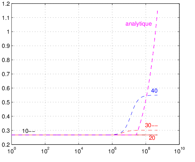
I took the chance to use Qucs as netlist simulator, and used ROM with different orders, comparing the results with the 'exact' solution from FastHenry2. Here you are my results:
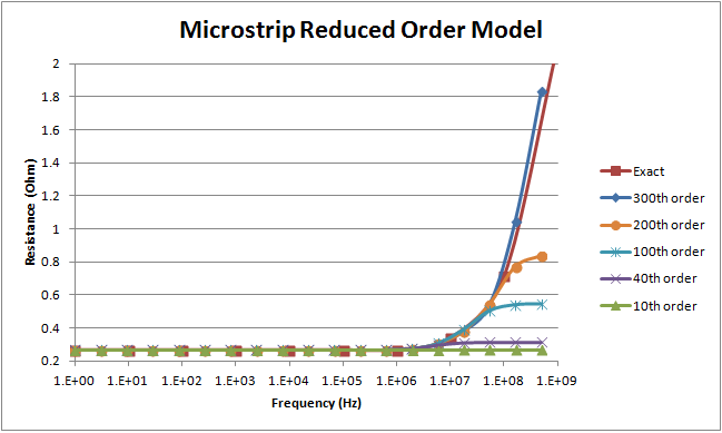
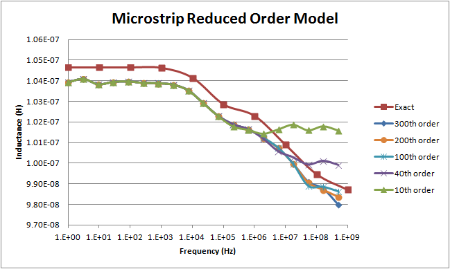
As you can see, the inductance converge for a lower order than the resistance does. However you must remember that the ROM generates a space state model that approximates at the same time both the inductance and the resistance. Now since the strip is relatively far from the plane, actually the inductance does not change much (don't be misled by the picture: note the scale!), while of course the resistance, due to the pure skin effect, has a knee and then increases as the square root of the frequency. So this situation is not so easy to approximate, and requires a higher order.
(another note: the 'exact' inductance and the ROM approximations have a small bias, but consider again the scale: this is well below 1%).
If you are interested I can share the Excel / Calc file as well as the Qucs schematic.
Best Regards,
Enrico
|
|
|
|
tomed
France
28 Posts |
Posted - Apr 13 2015 : 11:52:55
|
Dear Enrico,
Thank you for your answer and support.
I agree with the discretization of the trace, by choosing nwinc=11&rw=2, the smallest mesh should get about 2.7�m(as width) which is closed to delta(skin depth).
However, I still have some questions regarding your file:
Why is there 2 different values of nhinc?
With seg1=20, seg2=100. Why is skin depth matched for ground plane?
What do you mean by 'exact'results? How did you get them (analytical or another software)? If analytical, could you please tell me where I can find the formula you used?
Why have you changed the width of the ground plan from 100mm to 10mm?
[from Enrico][/from Enrico] VS [study][/study]
Also why have you changed the position of the trace? In your case, what about proximity effects especially in the case of the inductance?
Also, i've used this formula to get the frequency of skin effect beginning: fpeau= (4*rho)/(pi*mu0*t*t) with:
-rho:resistivity (ohm.m)
-mu0:permeability (H/m)
-t: trace's thickness (m)
For the study, fpeau=27.1MHz, got by analytical way.
By simulation, despite changing meshing parameters, haven't got this frequency, the maximum frequency got is about 3MHz.
Regarding inductance, Ldc is ok, by analytical way Ldc=1.055(10-7)H which is not so far from simulation results.
Anyway, since haven't found analytical formula for Lhf, it's difficult to get Lhf value for comparison.
Thank you, appreciate your time and support.
Best regards,
Tomed
|
|
|
|
Enrico
550 Posts |
Posted - Apr 17 2015 : 02:29:23
|
quote:
I agree with the discretization of the trace, by choosing nwinc=11&rw=2, the smallest mesh should get about 2.7�m(as width) which is closed to delta(skin depth).
However, I still have some questions regarding your file:
Why is there 2 different values of nhinc?
One value is used for the trace, that is only 25.4 microns thick.
The other one is used for the plane, that instead is 1.2 mm thick. So to 'see' the skin / proximity effect on the plane depth, you need a finer discretization inside the plane.
quote:
With seg1=20, seg2=100. Why is skin depth matched for ground plane?
Actually this is not only skin, it is proximity as well, but it will anyway happen at dimensions about the skin depth.
I reduced the number of seg1 to keep the simulation fast. The plane is anyway much larger than the trace, so reducing the dimension of the plane is not affecting in any significant way the result of the simulation, expecially when the frequency grows, and the current crowds under the trace (in this case, you could even use a much shorter backpanel)
quote:
What do you mean by 'exact'results? How did you get them (analytical or another software)? If analytical, could you please tell me where I can find the formula you used?
These are the direct results from FastHenry2, i.e. exactly what you see at the end of the simulation, and not the indirect results obtained through the generation of a ROM and its simulation.
quote:
Why have you changed the width of the ground plan from 100mm to 10mm?
See above
quote:
Also why have you changed the position of the trace?
So that it is still centered over the gnd plane
quote:
In your case, what about proximity effects especially in the case of the inductance?
See above
quote:
Also, i've used this formula to get the frequency of skin effect beginning: fpeau= (4*rho)/(pi*mu0*t*t) with:
-rho:resistivity (ohm.m)
-mu0:permeability (H/m)
-t: trace's thickness (m)
For the study, fpeau=27.1MHz, got by analytical way.
By simulation, despite changing meshing parameters, haven't got this frequency, the maximum frequency got is about 3MHz.
Actually I'm not sure about your factor 4 in the formula. If you take formula (2) in FastHenry's user manual, you can check the 'skin effect knee frequency' and you will find that this is lower. Anyway no analytic formula will predict the exact behavior of a complex set of conductors. This is why you should simulate.
quote:
Regarding inductance, Ldc is ok, by analytical way Ldc=1.055(10-7)H which is not so far from simulation results.
Anyway, since haven't found analytical formula for Lhf, it's difficult to get Lhf value for comparison.
You should be looking for microstrip inductance calculation via analytical formula.
Best Regards,
Enrico
|
|
|
|
tomed
France
28 Posts |
Posted - Apr 18 2015 : 14:48:39
|
Dear Enrico,
One more time thanks a lot for all your help and continuous support.
You're right regarding skin depth formula, I have to double check the analytic formula used to get skin effect knee.
With all the discussions, i've understood that regarding microstrip studies, i must have a careful look on the cross section (of microstrip and also ground plane), that's why the need is much focused on the thickness, am i on the right direction to understand?
However, i haven't correctly understood the ground plane thickness meshing.
With maximum frequency =500MHz, skin depth is about 3�m.
The ground plane thickness is 1.2mm. Using nhinc=11 means 11filaments regarding the thickness side, in this case what is the ratio between 2adjacents filaments?
Is it rh=2 like the default ratio?
I haven't understood why smallest filament is not so far from skin depth on the thickness of the ground plane?
Would you please like to help me understanding more?
Thank you, appreciate your time and support.
Best regards,
Tomed
|
|
|
|
Enrico
550 Posts |
Posted - Apr 21 2015 : 16:39:07
|
Yes, the default rh is 2.
Therefore, with nhinc = 11, we have (1+2+4+8+16+32+16+8+4+2+1)=94 as overall thickness in 'units' of the external filament, i.e. 1.2mm / 94 = about 12 microns
This is higher than the skin depth @ 500MHz but it is anyway in the range of, and you can check that even further increasing this value does not actually change the results, and only increases the simulation time (practical approach).
Best Regards,
Enrico
|
|
|
|
tomed
France
28 Posts |
Posted - Apr 24 2015 : 18:08:59
|
Dear Enrico,
Thank you for your help, i've now understood how to define correctly meshing.
I've tried with nhinc=9 rh=4 which matches with skin depth, long simulation time but no significant changes regarding the results.
Appreciate your time & continuous support
Best regards,
Tomed
|
|
|
| |
Topic |
|
|
|